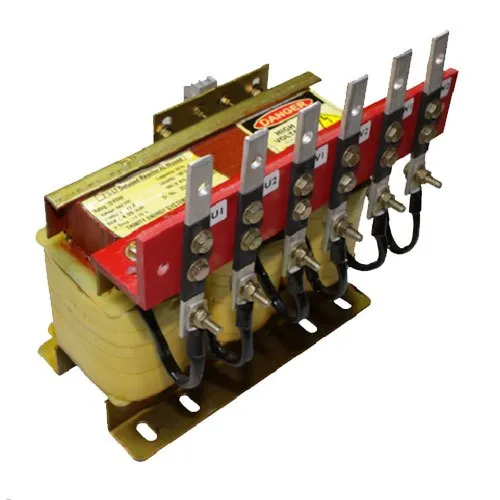
Harmonic
Consisting of capacitors, reactors and resistors, harmonic filter banks provide a low impedance route out of the system for harmonics. The series capacitor/reactor combination prevents resonance by tuning the network below the first dominant harmonic (usually the 5th or 300Hz).
- Harmonic filter circuit are designed as three-phase reactors with an iron core and air gap.
- Harmonic Filter Reactors are made out of highest quality material and very stringent quality control.
- It has been designed with properties like low temperature rise and lower flux density so that it can operate in worst conditions of ambient and harmonic overloads
- . They offer very good degree of linearity.
- Cheaper and non-linear reactors may trigger undesirable chain phenomena during periods of operation with high harmonic values, such as reducing in the inductance with consequent increase in the resonance frequency of the LC group,
- which would drain off more harmonic current, further reducing its inductance and overload the reactor more and more.
- Reactors are available with filtering factor of 5.67%, 7% and 14% in 12.5, 25, 50 and 100 KVAR rating. Any other filtering factor and rating can be made on request.
- High harmonic stress resistance
- Very low losses
- High linearity avoids “choke tilt”
- Low noise
- Long operating life expectancy
- With temperature protection (NC aux. contact
+ CONFORMS TO IS/IEC 60947-2&IEC 60947-2 & 3
+ CURRENT RATING FROM 400A TO 6300A
+ 50kA To 100kA Braking capacity
+ Available in 3 Pole/4 Pole
+ 100% rated neutral pole
+ Manually & electrically operated
+ Fixed & Draw-out versions
+ Protection through Thermal – Magnetic & Microprocessor releases
+ Self diagnostic Microprocessor based Releases with on-load testing through TEST button
+ High short time withstand capacity, Icu = Ics = Icw for 1 sec for total selectivity
+ High mechanical and electrical operating life
+ Data communication & Power Management


